
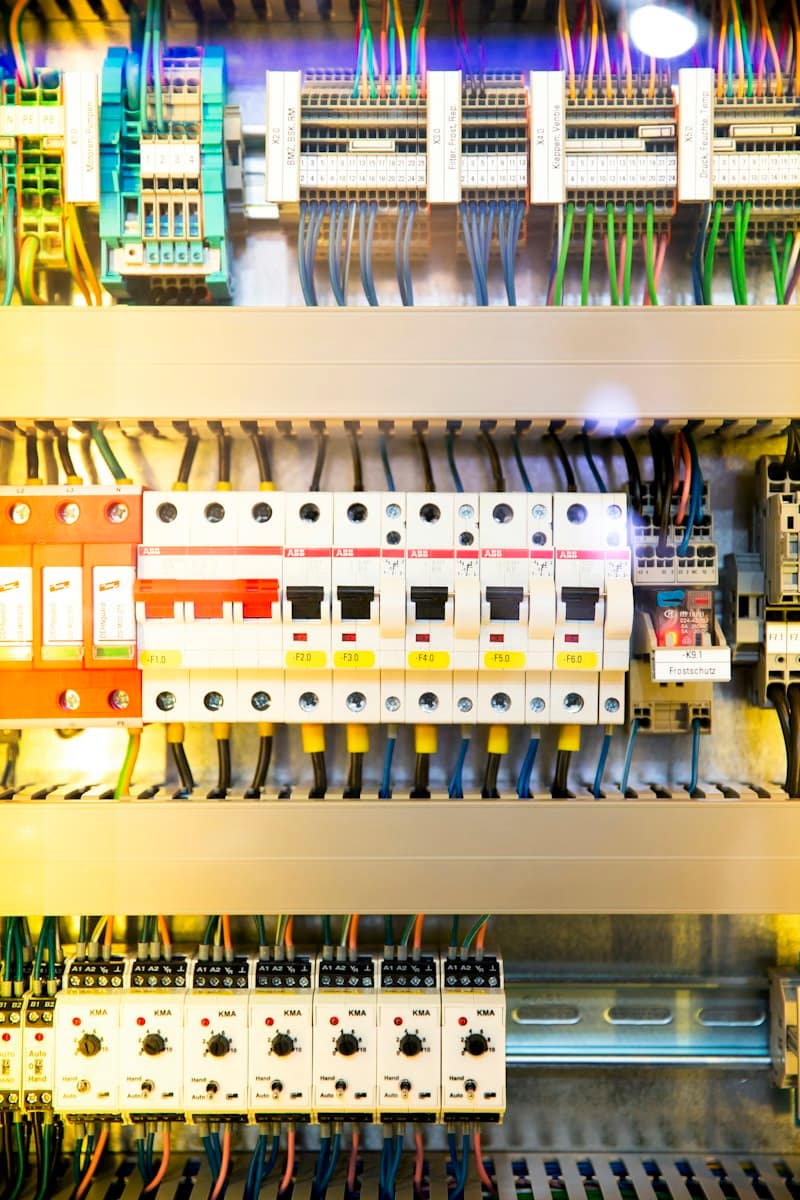
Power cable laying is the installation of LT and HT cables in trenches, ducts, trays or ladders, followed by proper termination and jointing. It includes route survey, trenching, bedding, tray fixing, heat-shrink or cold-shrink terminations, route markers and insulation and sheath tests. Done correctly, a cable runs for decades without maintenance.
At a glance
- Our scope
- Trenching, cable laying, trays and ladders, terminations, joints, route marking and tests
- Typical timeline
- 1 to 3 weeks per kilometre of trench route, depending on soil, crossings and weather
- Key standards
- IS 1255 for cable laying, IS 1554 and IS 7098 for cables, IS 3043 for earthing
- What you receive
- Route drawing, cable schedule, test reports and route marker records
- Best suited for
- Industrial estates, highways, solar plants and campuses
- Site survey
- Route walk, soil and crossing check before design
Power Cable Laying & Termination Overview
Power cables are the arteries of an electrical system. They are usually buried or hidden, which means mistakes are expensive to fix. A cable damaged during laying, a termination made without the right tools or a route that crosses a future pipeline can cause an outage months or years after the project closes.
We lay LT and HT power cables in underground trenches, in ducts under roads, and on trays and ladders in plants and substations. Work starts with a route survey, because the drawing rarely shows what is really in the ground. Existing pipes, drains, telecom ducts, rock layers and tree roots all shape the final route.
Termination and jointing are the most skill-dependent part. A cable lug crimped with the wrong die, a cut made too deep into the insulation screen or a gland that is not earthed can lead to partial discharge and failure. We use trained jointers, manufacturer-approved kits and tested tools, and we record each termination.
Shruti IT Service has laid power cables for industrial estates, highway projects, solar plants and campuses since 2014, based in Nashik and serving Maharashtra, Gujarat, Madhya Pradesh and Rajasthan. The same team installs panels, earthing and lighting, so cable ends land correctly in the equipment they feed.
Ideal for: Industrial estates, highways, solar plants and campuses.
What Our Power Cable Laying & Termination Includes
Our cable laying scope covers the path, the support, the ends and the evidence that the cable was handled and tested properly.
Trenching and cable laying
We excavate to the design depth, prepare a sand bed, lay cables with rollers and cover them with tiles or protective covers before backfill. Ducts are placed at crossings. Tip: ask for a spare duct at each road crossing, since breaking a road later costs far more than a pipe now.
Cable tray and ladder installation
Perforated trays and ladders are fixed with supports at specified spacing, bonded for earth continuity, and fitted with covers where needed. Tip: leave 30 percent free tray space for future cables, and keep power and signal cables on separate trays.
Heat-shrink and cold-shrink termination and jointing
Trained jointers prepare cable ends, crimp lugs with the correct dies and apply approved termination kits. Each joint is logged. Tip: ask for the jointer's name and kit batch on the record, because it helps trace any later failure.
Cable route marking and testing
We place route markers at turns and crossings, prepare an as-laid drawing and test insulation resistance and sheath integrity before backfill. Tip: store the as-laid drawing with the estate or site office, not only in your project folder.
Glanding, earthing and identification
Armoured cables are glanded and earthed, cores are ferruled and phases tagged at both ends. Tip: check that cable tags match the cable schedule, since swapped tags are a common cause of wrong phase sequence at commissioning.
Why cable systems fail after handover
Most cable failures start with handling. A cable pulled over a sharp edge, bent tighter than its minimum bend radius, or dragged on rough soil carries hidden damage. The test on day one may pass, and the fault appears after the first heavy load cycle or monsoon.
Poor termination is the second cause. Heat-shrink sleeves applied with an uneven flame, cold-shrink kits fitted on dirty surfaces, or lugs crimped with too few or wrong crimps leave a joint with high resistance. It warms, deteriorates and eventually fails. Installers often rush this part, since the cable itself looks finished.
The third cause is a route nobody remembers. Months later a contractor digs near the route and cuts a live cable because no marker or drawing exists. Route markers and an accurate as-laid drawing are small costs compared with an unplanned shutdown and a repair joint in the field.
What You Gain
Cable protected on the route
Sand bedding, tiles or covers, correct depth and duct crossings protect cables from digging, vehicle loads and rodents.
Reliable terminations
Trained jointers use approved kits and the correct crimp tools, and each termination is recorded, which reduces hot joints and partial discharge faults.
Correct current capacity
Cable size is checked against grouping, ambient and soil conditions, so the installed cable carries its load without overheating.
Traceable routes
Route markers and an as-laid drawing show where each cable runs, so future digging and expansion do not damage it.
Tested before energisation
Insulation resistance, sheath tests and, for HT cables, appropriate withstand tests are completed and recorded before the cable is energised.
Fewer shutdowns later
Quality in laying and jointing keeps the feed alive through the monsoon and summer peaks, avoiding repairs in the middle of production.
How the Work Is Delivered
Cable laying is staged so that routes are proven before excavation and every cable is tested before it is closed.
- 1
Route survey and design
We walk the proposed route, mark crossings with roads, drains and existing services, and check soil type. Cable size, number of runs, depth and duct needs are fixed in a route drawing and cable schedule.
- 2
Permissions and excavation planning
Road or highway crossings, municipal or estate permissions and utility locations are clarified. Excavation is planned in sections so trenches are not left open for long, especially in the monsoon.
- 3
Trenching and bedding
Trenches are dug to the specified depth and width, with a clean sand bed. Rock or hard soil may need extra bedding. Ducts are laid at crossings with spare ducts for future cables.
- 4
Cable laying and tray installation
Cables are rolled off drums on rollers with attention to bend radius and pulling tension. Trays and ladders in plants are fixed with supports at set spacing and bonded for earth continuity.
- 5
Termination and jointing
Cable ends are prepared, lugs crimped, and heat-shrink or cold-shrink terminations fitted. Straight joints are used only when needed. Glands are earthed and phases identified at both ends.
- 6
Testing and backfill
Insulation resistance and sheath tests are done before backfill. Cables are then covered with sand, protective tiles or covers, and the trench is backfilled in layers and compacted.
- 7
Route marking and handover
Route markers are placed at turns and crossings, and an as-laid drawing is prepared. You receive test reports and joint records, and thermography can be scheduled under an AMC.
How cable choice and termination affect life
LT cables are commonly PVC or XLPE insulated, armoured for direct burial, with aluminium or copper conductors. XLPE carries more current than PVC for the same size and handles higher temperatures. HT cables are XLPE with conductor and insulation screens, and their ends need stress control during termination. Current rating depends on laying method, soil thermal resistivity, depth and the number of cables in the same trench, which is why a cable that suits a tray may be undersized in a crowded trench.
Heat-shrink terminations use sleeves shrunk with a controlled flame, and need a clean cable surface and careful heating. Cold-shrink kits use pre-stretched rubber that contracts on release, which suits tight spaces and removes the flame risk. Either works if installed to the kit instructions. Armour is earthed through glands, and the screens of HT cables are bonded according to the design, so fault current has a defined return path.
IS 1255 for cable installation
Sets practice for laying, jointing and terminating power cables up to 33 kV, including depth, bedding, spacing and bend radius. We build our work method around it.
IS 1554 and IS 7098
These cover PVC insulated and XLPE insulated power cables. We specify voltage grade, conductor, armour and sheath for the environment and record batch details.
Minimum bend radius
Bending a cable tighter than its limit, commonly a multiple of overall diameter set by the maker, damages insulation and armour. We check radius at turns and terminations.
Current rating and derating
Soil resistivity, depth, grouping and ambient temperature reduce permissible current. We apply derating factors so the installed cable carries its design load safely.
IS 3043 for earthing of armour and screens
Armour and screens are earthed through glands and bonds, creating a defined fault path. Continuity is tested during commissioning.
A typical project: 800 metre feeder route across an industrial estate
A manufacturing unit needs a new LT feeder from a substation across an estate road to a new production block 800 metres away. The load is 250 kW, with future growth. A single cable would be heavy, so two parallel runs of armoured XLPE are chosen, in a trench with a duct crossing under the estate road and a spare duct for a future cable.
We walk the route and find an existing water line at one crossing and a rocky patch near the middle. The design adds extra depth at the crossing and sand bedding over rock. Trenching is planned in 100 metre sections so the monsoon does not leave long open sections. Cables are rolled out on rollers, with a checker watching bend radius at each corner.
Terminations are made with cold-shrink kits in the substation and heat-shrink in the field panel. Insulation tests are done on each core before backfill and recorded. Route markers go in at turns and at the road crossing, and an as-laid drawing is added to the handover file.
- Two cable runs laid with a spare duct for future growth
- Insulation test values recorded before backfill
- Route markers and as-laid drawing for the full 800 metres
- Termination records for every cable end
This is an illustrative scenario built from typical site conditions. Actual quantities, timelines and results depend on your site survey.
Power Cable Laying & Termination Across Four States
We are based in Nashik and deliver across Maharashtra, Gujarat, Madhya Pradesh and Rajasthan. Each state has its own utilities, approvals and site conditions, and these are the points that matter most for this service.
Maharashtra
Trenching in MIDC estates and along highways meets black cotton soil and basalt rock, which change bedding and duct needs. Monsoon rain floods trenches and shifts sand bedding, so we lay and backfill in short sections. Crossing permissions come from the estate authority or the road owner.
Gujarat
GIDC estates have dense underground services, so route surveys and utility drawings matter before digging. In coastal Kutch and Saurashtra, saline soil and high water table call for sheathed or armoured cable with sound end sealing, and duct crossings under busy industrial roads need planned traffic diversion.
Madhya Pradesh
Long cable runs inside large industrial areas and along the Delhi to Mumbai Expressway corridor may cross black cotton or murram soil. Black cotton soil swells and shrinks, so deeper bedding and duct protection at crossings reduce stress. Monsoon timing affects trench schedules.
Rajasthan
Dry sandy and rocky ground in RIICO estates and solar parks changes soil thermal resistivity, which affects cable current rating, so we check derating for dry soil and depth. Rock cutting slows trenching, and termination work in strong sun and dust needs shade and clean surfaces.
Where This Work Is Most Often Needed
Why Teams Work With Us on This
Route walked before it is dug
We survey crossings, soil and existing services on foot, which prevents surprises that stop a trench halfway.
Jointers and kits matched
Terminations use approved kits and the correct tools, and each is logged so the quality can be traced.
Same team for panels and earthing
We install the panels and earthing that cables connect to, so glanding, bonding and tags are consistent.
As-laid records you can use
Route drawings and markers are handed over so later digging and expansion do not put your feeders at risk.
Need AMC for an existing system?
We maintain installations done by other vendors too, after a short audit of what is already on site.
Guides and Projects Related to This Service
- ArticleSizing a Rooftop Solar Plant and Checking Its Payback: A Worked Example
- ArticleWhat to Ask Before You Sign an AMC: A Checklist for Buyers
- ArticleHow to Size a UPS and Battery Bank: A Worked Example for a Small Server Room
- ArticleVoltage Drop in CCTV Cable: Choosing the Right Size for 12 V Cameras
- ArticleIndustrial Electrical Infrastructure: Earthing, Panels & Safety Compliance
Frequently Asked Questions
01How deep should underground power cables be laid?
LT cables are commonly laid at around 0.75 metre depth, and HT cables deeper, often 1 metre or more, with greater depth at road crossings. The exact depth follows IS 1255 and site conditions. Cables sit on a sand bed, covered with sand and a protective layer such as tiles, with markers on the surface.
02What is the difference between heat-shrink and cold-shrink terminations?
Heat-shrink sleeves contract when warmed with a controlled flame, while cold-shrink sleeves are pre-stretched and contract when the support core is removed. Cold-shrink needs no flame, which helps in confined or hazardous spaces. Both perform well if installed to the maker's instructions on a clean, correctly prepared cable end.
03How long does cable laying take?
Roughly 1 to 3 weeks per kilometre of route, depending on soil, crossings, permissions and rain. Rock and road crossings slow the work. Termination and testing add days. We split trenching into short sections so the route is never open for long, which matters in the monsoon season in Maharashtra.
04Should I choose aluminium or copper cables?
Aluminium suits large LT and HT feeders because it is lighter and cheaper per ampere, while copper suits smaller circuits and compact spaces because it has lower resistance and better joint behaviour. Aluminium needs proper lugs and anti-oxidant treatment. The decision depends on size, budget and termination space in the panels.
05How do you test a power cable before energising?
We measure insulation resistance between cores and to earth with a megger at a suitable test voltage, and check armour and sheath integrity. HT cables may also need a withstand test set by the specification. Values are recorded on a signed sheet. Retest after backfill if a section was disturbed.
06What documents should I get after cable laying?
Ask for a cable schedule, as-laid route drawing with depths and crossings, insulation test reports, termination and joint records, drum numbers or batch details, and route marker locations. These let you trace any fault, plan future digging safely and prove to inspectors that the installation followed the specification.